Relays are common in control circuits, appliances, automotive systems, and industrial equipment. When a relay starts to fail, devices may not switch as expected, or power may flow where it shouldn’t. Knowing how to test a relay with a multimeter helps you isolate problems quickly without pulling the whole system apart. This guide explains clear, safe steps to verify coil resistance and contact continuity, so you can decide whether to replace the relay or continue troubleshooting other components. For a direct, hands-on procedure, see the dedicated guide how to test a relay with a multimeter.
Safety and prerequisites
Before you begin, disconnect power from the circuit and discharge any capacitors in the area you’ll test. Use a digital multimeter with a fresh battery, and set the meter to appropriate ranges for resistance (ohms) and continuity. Wear eye protection when working with energized systems, and never energize a relay while you are probing exposed pins with a meter unless you are certain you know the coil voltage and can safely apply it.
Tools and items you’ll need
- A digital multimeter capable of resistance, continuity, and, if possible, current (for more advanced checks).
- The relay under test, with clearly labeled coil and contact pins or a datasheet.
- A known-safe power source that matches the relay coil voltage (for energizing tests, if required).
- Connecting wires or alligator clips to keep pins accessible during measurement.
Testing steps
- Identify the relay’s coil pins. If you have the datasheet, confirm coil resistance spec.
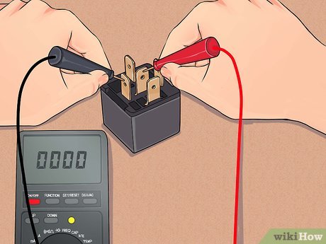
- Measure the coil resistance with the meter’s resistance/ohms mode. Compare the value to the datasheet. A coil that is open (infinite resistance) or shorted (near zero) indicates a faulty coil.
- Check contact continuity without energizing the coil. Use the COM and NO pins; you should see no continuity between COM and NO when the relay is de-energized. Check COM and NC; you should see continuity between COM and NC when the relay is de-energized.
- Apply the coil voltage if safe and practical. Energize the coil with the rated voltage for a brief moment and observe the change in contact state. NO should connect to COM, and NC should open.
- Without removing power, you can test the response time and bounce using the meter’s continuity mode, if your setup allows. This is a quick sanity check, not a replacement for functional load testing.
Common pitfalls and tips
A few practical hints help improve accuracy and reliability when testing relays with a multimeter:
- Avoid testing a live circuit. Energizing a relay while probing can damage the meter or cause shorts.
- Double-check pinouts against the datasheet. Relay packages vary, and a wrong pin choice can mimic a fault.
- Corrosion or dirt on contacts can hide poor conduction. If symptoms persist, clean contacts or replace the relay.
- Perform multiple cycles of energizing and de-energizing to reveal intermittent contacts or welding.
- Keep a record of coil resistance and contact behavior for future diagnostics, especially in fleet or production environments.
If the coil or contacts fail to meet these checks, the relay is unreliable and should be replaced. If results are mixed, recheck the wiring and ensure you’re testing the correct pins, which can vary by package type. For additional tips on selecting a robust relay and interpreting datasheets, visit the Magazetter homepage.
By following these steps, you’ll gain confidence in diagnosing relays and preventing downstream failures. Remember that relays are mechanical devices with several moving parts, so occasional corrosion, dirt, or welding of contacts can alter performance even when the coil still tests within spec. Regular checks, especially in critical control circuits, help extend equipment life and reduce unexpected downtime.